Light controlled Robot without using Microcontroller
Difficulty Rating : 1/10
First Self designed Robot
Based on LDR based light sensing module
Based on LDR based light sensing module
Description:
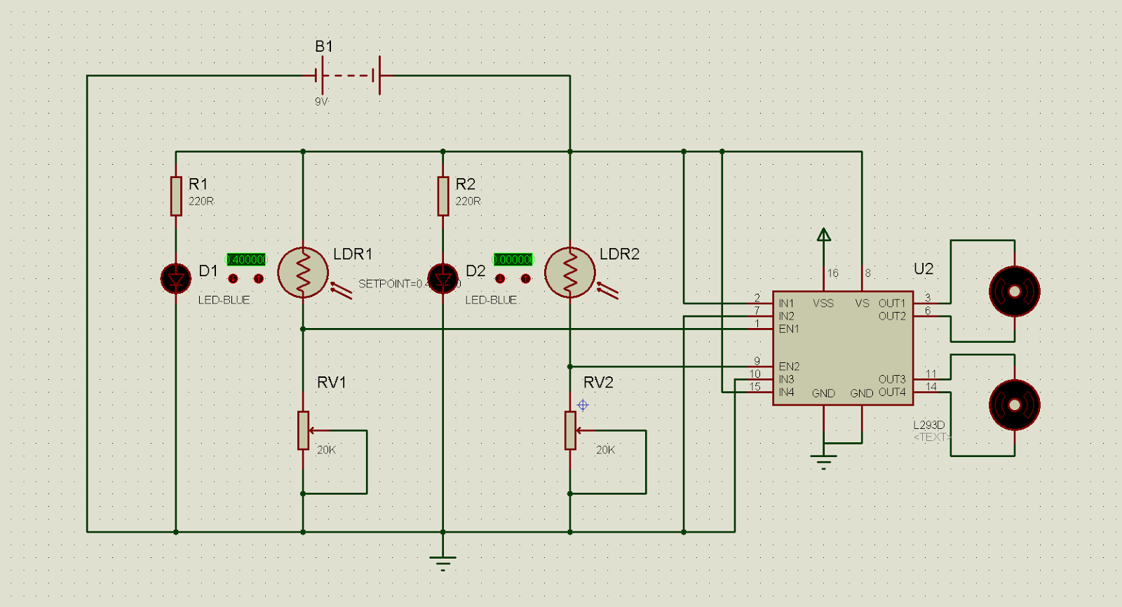
This circuit is specially designed to make a Robot that can be controlled using light.Works best with a laser light .LDR or light dependent resistor is a resistor which has high resistance in dark (a few megaohms) and low resistance in light. Using this principle two kind of circuits can be implemented viz. photovore(Light activated) & photophobe(dark activated).
The module shown below acts as a photovore.The variable resistor adjusts the intensity of light at which the transistor switches ON. So when light falls on the left ldr, left motor will get activated and when light falls on right ldr right motor will get activated, depending on how you attach the motors.
Components:
- light dependent resistors (LDR)-2
- 2.7Vz Zeners(Recommended, but not required)-2
- Diodes 1N4004_1N4007 (any)- 2
- General purpose transistor(SL 100 or 2N3903)-2
- 10K pots-2
- low rpm DC motors-2
- wheels-2
- 2pin connectors(Recommended, but not required)-2
- Chassis-1
- Any 9V battery-1 or 2
- A general purpose PCB (Veroboard)
 |
| My prototype |
This module is fit to be called a 'light sensing module'. But still there are some technical glitches occuring because of the less efficient components.
Note: The multi-revolution trimpot used in this circuit is one of the best variable resistors of its kind up till now.This circuit does not include 'digital' components in it, the very reason behind its low accuracy.
The motor is a bi-directional electrical component. Here, we are using it to run in one direction only, and hence we are using the Diode. This diode also helps from protecting the supporting motor circuitry from excessive current drawn.
This circuit can be upgraded to a Line follower robot (Without using microcontrollers ) just by adding a high power LED. Also an additional driver can be added to boost its performance.
Just drop a comment if you have any doubts, or if you are stuck-up at any concept.


Comments
Post a Comment