Posts

Line Following Robot- Using Microcontroller

Difficulty Rating: 6/10 Inspiration: Well, the Microcontroller-less Line following Robot turned out to be a huge success & earned a big name, and now its time to move on, to make bigger things. And this time its Line following Robot Using Philips Microcontroller P89V51RD2 (8051) a controller similar to Atmel's AT89C51. Components used: 1. 8051 Minimum requirement kit This kit consists of all necessary components like MAX232, DB9 connector or RS232, 11.0592MHz crystal, capacitors, Power supply unit etc. 2. AT89C51 or P89V51RD2 3. Motor driver L293D 4. InfraRed sensor CNY70 It consists of both transmitter-receiver inbuilt 5. LM324 6. LED 7. Resistors 8. Trimmer 9. Geared Motors 10. Wheels 11. Chassis 12. RS232 cable 13. 9 V supply 14. Other secondary hardware stuff (nut-bolts, screw, metal clamps etc.) 15. 16x2 LCD (optional)

The homemade 'green' LED tent light (Design + field test)

Image
Recently I went looking for a small portable tent-light, that can be used during camping and overnight treks. I was targeting the LED's with a heat sink attached to it. I found a variety of such devices but they were not worth the price I was going to pay. Most of the devices used the 3xAAA size batteries which are quite inconvenient to use, especially in India. So I decided to make something much cheap, at home and as I want it to be, in terms of size, shape, circuit complexity etc.  This time decided to something with the used batteries. Re-generating the wasted energy with the Joule thief ! Hence the name 'Green'.  Knob on the left side is to control the intensity. Right side is the switch. I have used a small wire to complete the circuit You can see two small PCB's mounted inside.   Ultra bright LED!! Once done, I put the setup inside a used plastic shampoo bottle. Used the empty space to keep the spare batteries as well as to maintain the b

Speech, Text Controlled Robot using ARDUINO and VB.Net

Image
Difficulty Rating: 8/10 (Requires basic VB.NET skills) VB.Net and ARDUINO STAGE I: This is the basic setup of the Speech/Text/Computer controlled Robot. The commands are sent serially over the USB to the ARDUINO Duemilanove. The corresponding signals then drive the two 300 RPM motors with the help of a motor driver IC L293D. STAGE II: Introduced a RF module so that the Robot can be wireless operated, with only the Receiver mounted on the Robot. The transmitter transmits the signals with the help of ARDUINO and the signals are received by the Receiver on the Robot, which controls the motion of the Robot. Video of the Software Implementation (Software part): Video demonstration of the speech commands to the robot (Software part): Video demonstration of the full project (Hardware + Software): This is the video of the Computer controlled robot which has following features-- Speech command input Text command in

Bend Sensor- Initial iterations and testing

Image
This is the video of the bend sensor designed at the lab for a project on 'Sensor based systems' course at KTH. This is the initial testing of the first such sensor made. The final demonstration:  Left hand controls the down-motion (brake) and the right hand controls the acceleration (move forward). Focus of the project was on the sensor-characterization and testing them for repetability, precision etc. In the video, you can see the Sensors in action. The small green board is the USB keyboard driver board, scrapped from an old dell keyboard. The blue components are solid state relays. 

A totally random robotics experiment

Image
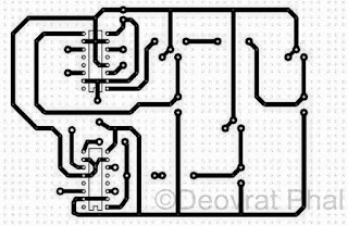
RF Module (Tx, Rx), LDR's, L293D, PCB manufacturing kit (to design PCB at home), Basic robot chassis Plan was to control the robot using LDR's basically a light operated robot kinda thing. The driver part was designed and fabricated at home. The PCB layout of the driver part The etched PCB board PCB board with components The controller part with LDR and RF module All parts attached  

Happy Diwali (The Engineers way)

Image
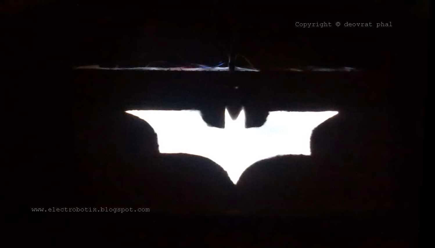
Its Diwali- the festival of lights! And speaking of lights, I thought that making a LED project would be a best tribute to Isamu Akasaki, Hiroshi Amano and Shuji Nakamura for their 2014 physics Nobel Prize. So its just a small LED project. Lets summon the Batman this Diwali !! The Bat-lantern in action ! To avoid the intricate circuitry I used a 12V SMPS adapter and a 5V regulator with two capacitors at input and output. Five LED's seems to work perfectly to make the bat-signal . The logo which I used is the one from 'The Dark Knight' movie. And the result was- a super awesome Bat-Signal-Lantern. Happy Diwali !!

Interface for Advance Robotic Controller (iARC) Version 1.00 & 2.00

Image
Difficulty Rating: 7/10 GUI Design: VB.NET Microcontroller Board: ARDUINO Duemilanov (AtMega 328) Features: Speech Commands, Text commands, Button Commands, Fully Autonomous Mode Used for: Robotic Car (iARC V1.00), Robotic Arm (iARC V2.00) The GUI is designed on Microsoft visual studio 2010 using VB.Net. The commands are serially sent to the ARDUINO Duemilanove, which controls the Robot car. The baud rate is set to 57600bps, which can be changed as per the user convenience.  I've also added a "Serial communication tester button" to ensure the flawless communication. It simply lights a LED when the serial communication takes place. Properties used to build the code: Baudrate: To set Baud rate Eg. 9600, 57600 Databits: Standard length of databits per byte Encoding: Byte encoding for pre and post transmission of conversion of text Handshake: Handshaking protocol for serial communication IsOpen: V alue indicating the open or closed status of the  Serialp