Line follower Robot - without using Microcontroller!!
Difficulty Rating : 3/10
Ever wanted to make a Line follower Robot, 'without' using Microcontroller ???
Then you have visited a right place.
Inspiration:
Components :
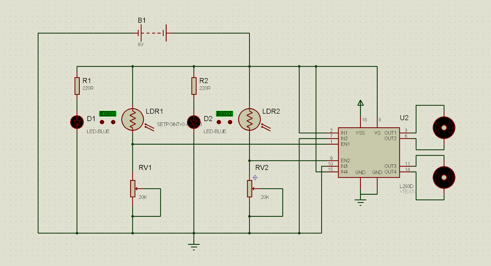
Circuit diagram:
The Circuit diagram with four pairs of LED-LDR. Click on the image for full-size version.
Working principle:

Feel free to comment if you are stuck up, or want to know more about its designing aspects, or if you find any bugs in the circuit diagram.
Ever wanted to make a Line follower Robot, 'without' using Microcontroller ???
Then you have visited a right place.
Inspiration:
I stumbled upon this Robot in my First year of Engineering during one of the Intercollegiate Robotics Championship (Regional) and ever since, it was my dream to make this Robot on my own. I googled for it & got many designs, but all Microcontroller based. I even shortlisted a few but my senior Pratik Kamat asked me take small steps first and suggested me to make one without the use of Microcontroller and with self designed logic.
Now, as a part of Electronics workshop in Sem-IV (II Year), we were supposed to make a project based on 'Electronics'. Since I was introduced to Microcontrollers at that stage, I made a proposal to make a Microcontroller based LFR( Line follower Robot). But it was rejected by my Batch in-charge as no microcontroller based projects were allowed for current semester. So i decided to make a LFR without using microcontroller. So, started the designing...
Now, as a part of Electronics workshop in Sem-IV (II Year), we were supposed to make a project based on 'Electronics'. Since I was introduced to Microcontrollers at that stage, I made a proposal to make a Microcontroller based LFR( Line follower Robot). But it was rejected by my Batch in-charge as no microcontroller based projects were allowed for current semester. So i decided to make a LFR without using microcontroller. So, started the designing...
And to my surprise, the design was not that tough as it looks. All my friends loved it, batch in-charge appreciated it & (what startled me was the fact that) my immediate Seniors couldn't understand the working at all !!!!
Components :
- High power LED (5mm) - 2 to 4
- LDR's -2 to 4
- Preset 20k -2 to 4
- 220 Ohm Resistors -2 to 4
- L293d -1
- Geared motors -2
- Chassis
- 4.8V NiMh rechargeable battery
- Burg strip, 2 pin relimat & other secondary stuff..
Circuit diagram:
The Circuit diagram with two pairs of LED-LDR. Click on the image for full-size version.
 |
| Click Image for Enlarged View |
The Circuit diagram with four pairs of LED-LDR. Click on the image for full-size version.
 |
| Click image for enlarged view |
 |
| Click image for Enlarged view |
Working principle:
Our 9th grade science book has taught us that, when light falls on white surface, it gets reflected. When it falls on black surface (or any dark surface) light gets completely absorbed by it. How is this concept applied here? The sensor module has two LED-LDR sensor pair mounted on it (Minimum two is required. You can use any number). The LED or light emitting diode is a semiconductor light source which we will be using. I had used a 5mm white LED for my project. Also, LDR or Light dependent resistor is used here as a Light sensor. It senses the reflected light; i.e light transmitted by the LED and reflected from the surface. If the surface is white, LDR will detect the light. In case the sensor is placed over black surface, LDR cannot detect any light, as the black surface has absorbed all the light.
How Robot follows Line:
(Here I have used two LED-LDR sensor pair instead of four)
Please try to understand that the Left sensor-pair is connected to the left Motor and Right sensor-pair is connected to the right Motor. Notice that the sensor (Either left or right), from which the arrow is pointing outwards is our white LED (transmitter) which emits white light and the one on which arrow is pointed to is LDR or Light dependent resistor (Receiver). This LDR detects the amount of light that will get reflected from the surface, depending on whether the surface is white or black-line.
How it Works:How Robot follows Line:
(Here I have used two LED-LDR sensor pair instead of four)
Please try to understand that the Left sensor-pair is connected to the left Motor and Right sensor-pair is connected to the right Motor. Notice that the sensor (Either left or right), from which the arrow is pointing outwards is our white LED (transmitter) which emits white light and the one on which arrow is pointed to is LDR or Light dependent resistor (Receiver). This LDR detects the amount of light that will get reflected from the surface, depending on whether the surface is white or black-line.
 |
| Straight |
 |
| Left turn |
 |
| Right turn |
This
Line Follower Robot basically use a Cadmium Sulphide (CdS) photocell sensor or
known as Light Dependent Resistor (LDR) and the high intensity white Light
Emitting Diode (5mm LED) to illuminate the area under the LDR sensor to sense
the black track line. The LDR will decreases its resistance in the presence of light and
increase its resistance in the dark. The region under the LDR is illuminate
with a high intensity white LED, the white surface will reflect most of the
light to the LDR surface while the black track line will absorb most of the
light, therefore less light will reflect to the LDR surface. The
20KOhm trimpot and LDR basically is the voltage divider circuit. When the LDR
detects the black track line it will receive less light intensity (LDR
resistance increase). Result, the geared DC motor will turn slowly or stop. When
the LDR on the white surface it will receive maximum light intensity (LDR
resistance decrease) . Result, the geared DC motor will turn fast.
The IC L293D is a motor driver IC, used for boosting current levels, large enough to 'drive' the DC motors.
This is the pic of my 1st prototype using Breadboard (2 LED-LDR sensor)
This is the pic of my 1st prototype using Breadboard (2 LED-LDR sensor)
 |
| The sensor mounting |
Here's the video of my first Test-Run :
Feel free to comment if you are stuck up, or want to know more about its designing aspects, or if you find any bugs in the circuit diagram.


frnd my name is ritesh....
ReplyDeleteim interested in making this bot .......
can i get photo of this bot
mahato.ritesh45@gmail.com
Check your mail.
ReplyDeleteGOOD WORK.......
ReplyDeletei want to make this robot ,,but there are two things which i cant understand
ReplyDelete1)connections of third pin of potentiometers
2)there are two batteries of 6 volt nd 9 volt.....but on component list ,,this is not mentioned.
also mail me the photo of this bot
and reply to my question...
my mail id is
farazshahid51@yahoo.com
u can also 4th pin for the potinometre :P
DeleteYou can use any available battery...
ReplyDeleteI didnt use 9V battery.
Check your mail for other details.
i want to make this bot
ReplyDeletebut it should be fast
so i was thinking of using a 12 volt battery and a transistor
can you pls give me any suggestions to make this bot more accurate
my mail id is saiprakash35@gmail.com
If u want more speed, use a motor with 300+ rpm..ut u wont get more accuracy wid that...
ReplyDeleteIf u want it more accurate, use a 60 rpm motor....
If u want both in 1 (i.e. both speed n accuracy), go for microcontroller based one..
can u bot me this?
ReplyDeletemy email : k.huda01@gmail.com
hey can i get the circuit diagram and video of this bot.. at
ReplyDeleteer.saurabh90@gmail.com
for my project i want to make dis bot. Can you send me the necessary details at
ReplyDeletecoolsprateek@gmail.com
can you send the detail at kameq_haidir@yahoo.com
ReplyDeleteHey Prateek,
ReplyDeleteCheck ur mail.
Best of luck for your project.
Hey Haidir M,
ReplyDeleteCheck your mail
hi,i'm sahrul...can u email me all important detail about this robot...? Interested in making one robot like this. this is my mail rules_2408@yahoo.com
ReplyDeleteTQVM :)
hi m Utsav tripathi m intrstd in this bot... can i have the details on writetripathi@gmail.com ..???
ReplyDeletecan you tell where all these connections go?? i am going crazy with dat daigram. srinagrao96@gmail.com - my id. pls say in words how to conect all the things :p thnkz in advance
ReplyDeletehello,
ReplyDeletei get confused with the position of LED & LDR
1) LED LDR LED LDR ///BLACK/// LED LDR LED LDR
///LINE///
2) LED LED ///BLACK/// LED LED
LDR LDR ///LINE/// LDR LDR
3) LED LDR ///BLACK/// LDR LED
LED LDR ///LINE/// LDR LED
which one is correct?
or have another position?
please tell me
thank you
this my email manufc_15@yahoo.com
Hey Muhammad Osman, check your mail.
DeleteEnjoy
I've designed a similar line follower using IR Led & Photo-transisitor couples... But the problems is with just two of these sensors the bot is unable to make sharp 90 deg turns most of the time..
ReplyDeleteCan u please help me regarding this problem?
How many sensors do i need??
I want to design the bot without microcontroller..
Please tell me..
Thanks in advance :-)
My Mail: hunk4mhell@gmail.com
Increasing the number of sensors wont ake any difference..
DeleteFor accuracy, you need to trade-off a parameter..i.e. speed....
For that use less RPM motors (~ 10-60rpm)
hi thats akshay
ReplyDeletei want to make the same project ,i want to make dis bot. Can you send me the necessary details at ratan.akshay@gmail.com
Hey, I've updated the blog.. check it..
DeleteEnjoy!!
can you please send me the details of this project along with its photo as I want to make this project.
ReplyDeletemy id is gs7560@gmail.com
Hey, I've updated the blog.. check it..
DeleteEnjoy!!
i'm intrested in this project can you send me its details at prateek_17@ymail.com thanks..
ReplyDeleteHey, I've updated the blog.. check it..
DeleteEnjoy!!
plz send me the more detail; and circuit diagram,i am in 1st year in my mechatronic engineering,plz suggest me if i submit its proposal can i made it easily.
ReplyDeleteHey Imran, everything u need is on the blog.. If you are not comfortable with any aspects, then don't hesitate 2ask..
DeleteEnjoy
i am interested in this project ...plz send me the circuit diagram and equipment for simplest to simplest circuit...because i want it just for curves..not for joints,,or 90 degree turns
ReplyDeletemy mail id
imran.bhachar@gmail.com
Hey, refer the 2LED_LDR sensor circuit diagram...
DeleteThat'll help you..
can u mail me the complete details plz
ReplyDeletepranu.cool11@gmail.com
Hey, I've updated the blog.. check it..
DeleteEnjoy!!
Mind sending me more details related to this project and ckt diagram also plzz..
ReplyDeletemy mail id is arunjangid714@gmail.com
Hey, i've tried to add max. details here itself..
DeleteU can download/view fullsized circuit diagram by clicking on the image.
If you have specific problem regarding its making feel free to ask..
--Deovrat
Hey i wana make this bot......but which battery is suitable for more accuracy and for average speed...plsss mail me all these detail on my mail id... singharyan01234@gmail.com
ReplyDeleteIts not about the battery..
DeleteFor accuracy use less rpm motors (say 100rpm) ...
Average: use 200-300rpm, but it cant take sharp turns....
Its a trade off between speed & accuracy
..
Battery I would prefer Rechargeable Ni-Cd 4.8V or a simple 9V battery can also work...
Be sure to use high torque motors..
Hey deovrat, I am making this bot of yours..
ReplyDeleteCan u plz send me the complete detail of the components ( motor, LEDs, LDRs, etc ) to my email id.. and also suggest how the arrangements of the 4 LED-LDR pair bot..
My email id is : shreenagaral@rediffmail.com
Hey, I've updated the blog.. check it..
DeleteEnjoy!!
HI FRIEND
ReplyDeletei really impressed on this bot shall i get the circuit diagram for this bot
my mail id is : praveenkumardotc@rediffmail.com
Hi there,
DeleteThanks...
The circuit diagram is available here, on this blog for free!!
Just click on the diagram for full size view.. and download it!!!
Anything else??
if i can use any other motor and i got the output but there is no turing
DeleteWhich diagram are you referring? two sensor pair or four sensor pair????
Delete..
Did vary the trimmer pot?? Using trimmer pot you can control the turning...
Also mail me your bot pics, so i can guide you better p.deovrat@gmail.com
kindly do mail me he details please
ReplyDeleteheraldbaby5@gmail.com
Hi, do u want explanation on specific part of d bot??
Deletei'm interested in this bot for my college project pls send details to prateek.kukreja2012@gmail.com
ReplyDeleteHi, glad u're intrested!!
DeleteDo u want explanation on specific part of d bot??
hi deovrat phal
ReplyDeletei'm interested in this bot for my college project.
can i have some further explanation in making this bot?
can you send me some information in how you make it?
please send me a details
THANK YOU
fvince09@yahoo.com
helo deovrat for my major project i want to submit this line follower bot so can u plz send the data that what is required n how to combine this all ......i need to make this project till 9 feb...mine email is lokesh_46@rocketmail.com
ReplyDeletewhat if we want to follow the white track!!
ReplyDeleteThat will completely change the circuit diagram...
DeleteU'll have 2 use LDR's as a dark-activated switches, and also interchange sensor & motor connections also...
what if I want to build a car which follow a white line what should I use?
Deletemy email is : ayy.ghayy@gmail.com
how many wheels does the robot use? i only see two. what happens if i use another wheels but this wheel will not be connecte to a motor will only be for stability? could affect the movement with that wheel? P.S I'm not English speaker
ReplyDeleteThe motion is based on concept of differential drive. If u use extra set of wheels, that will only cause disoriented motion. So usingg 2 wheels and a castor wheel is d best option.
Deleteactually i am participating in my clg fest..so i need to make such awsme bot..atually its my first time so im not able to understand it properly..can u help...plz..my id (jitesh_nagda@yahoo.com)
ReplyDeleteHey, what part is not understood? I'll try to make it more easier if i could knew..
Delete--Deovrat
hey..What would be the circuit diagram for the same high speed lfr using LM 339? please mail me the circuit diagram at jjayya@gmail.com
ReplyDeleteU wont get speed with LM339. Only it'll add a bit of accuracy.
Deletedud , need the exact details of this !!! i need it for my mini project!
ReplyDeletemail me at sachink.student@gmail.com
Hey most of it is mentioned here... Any further explanation needed on any part?
Deleteplz sir can u mail me the other details to ramsanjay83@gmail.com
ReplyDeleteawesome dude ..can u mail me the other details to ramsanjay83@gmail.com..
ReplyDeleteThnx..
DeleteBut do u want any particular aspect in detail?? Coz i've tried to explain everything in here..
how much rpm of motor u used.????
ReplyDeleteI used 300 RPM motor
Deleteplz send how make a sensor .my email id is yogilpu@gmail.com
ReplyDeleteHey, you would need a general purpose PCB for sensors, which contains only LED-LDR======LDR-LED ..
DeleteTake out respective connections out, and connect them asper the diagram..
plz send me d complete circuit diagram of dis bot...nd d related images...email: akash.56789@gmail.com
ReplyDeleteHey, can you also post your design circuit with microcontroller? Thanks
ReplyDeleteYeah, sure...
DeleteJust gimme a day or two..
--Deovrat
@deovrat,
ReplyDeletei wanna make driverless car but at initial stage i have to make this line follower and speed is not required so by this circuit diagram if i make..it will surely work as i havent any more time..
and can u mail me all details,diagrams,datashit and all?
my email id is "urvishmehta92@yahoo.com"
yes i also wnt to same project :( but i hv less information for this so plese if you hv some informtion ie citrcuit diagrm so plz text me on my this email
Deletezahidhussain056@gmail.com
I have included most of the information here on this blog.
DeleteI hav a habit of updating the info constantly. If u are facing a problem in specific area, do lemme know.
..
About ckt diagram, go for two sensor model.. you would need datasheet for L293D (Motor driver IC)..
..
It can be easily implemented if u are thorough with the circuit diagram.. so if u have any doubts then lemme know asap..
..
Best of luck to both of u..
--Deovrat
Please tell me completed components list
ReplyDeleteand also show the rpm of Dc motor.
Email: latif_mak2010@hotmail.com
Dear it is Amazing. i appreciate ur work.
ReplyDeletei m teaching in normal high school. i want to do this kind of projects in my school.
i expect ur positive reply. my id is lakeerpatel@gmail.com
thanks a lot...!! :)
hi my name is emre. i have a project about line follower robot. can you send me details about this circuit.
ReplyDeletemail : ealtinsoy92@gmail.com
Thank You...
Hi, I have mailed you the details.
DeleteHarsh Arora:- Plz send the entire project report alongwith d ckt diagram asap at:- harsh.arora800@gmail.com
ReplyDeleteplzz help dear friends im doing a project on line following robot without using microcontroller in also includes an remote plz send me the entire project with block diiagram and the pcb layout to abinj9@gmail.com send me with 2 or 3 days its urgent
ReplyDeletehey can u please send me the details of the circuit and how to build it??
ReplyDeletethnks..
karankaushal94@gmail.com
Hey karan, I have mailed you the details.
Deletehey:kindly send me details for making this bot.
ReplyDeleteasim_shah9066@yahoo.com
Can you kindly send me the details to make this robot.. Need help for the project.. My mail drag6936@yahoo.com
ReplyDeleteI want to made this robot
ReplyDeleteplease send me the necessary Details
My email id is
raviparjapati@gmail.com
Hello sir
ReplyDeleteI want to make this project please send me the necessary details on my email id raviparjapati@gmail.com
nice project...
ReplyDeletewhere will the pin 16 goes to.....?????????
ReplyDeleteHey Thanks..
DeletePin 16 Goes to VCC or Battery (power Source) you are using
what are ground pins????
ReplyDeletePin No. 4,5,12 & 13 are ground pins..
Deleteshould we connect all ground pins??
ReplyDeletePin 4, 5, 12, 13:
DeleteThese pins are ground pins. They form an on-board Heatsink. Usually these pins are to be shorted & connected to ground.
But, I insist, take a multimeter and test the connectivity of these pins. THEY ARE INTERNALLY SHORTED. We need not short them again, it'll only increase the wire-do of your circuit.
http://electrobotix.blogspot.in/2013/03/l293d-notion-to-be-cleared.html
hey dude.... nice job
ReplyDeletecan you mail me the construction of the bot..... please
thanxxxx
Kuldeep.maurya15@gmail.com
Hi! Thanks..
DeleteI'll mail u as soon as my semester exams get over..
Also, i'll upload it on this blog..
Hi, check your inbox..
Deletehey...can you mail me the bread board connections closely.....
ReplyDeleteActually I removed the bread board connections long back after my trial run..
DeleteBut check the blog now..
I have uploaded a Fritzing diagram..
Also, whats ur email id?
Deleteranadheerforrace@gmail.com
DeleteDear , I need Pics of ur bot ,
ReplyDeleteCan you send me ?
I will start making this thing on this saturday ,
Do you have watsapp or wechat to contact you directly through mobile ?
sadiq.soomro@yahoo.com
my email
My contact number
Hi,
DeleteYou can leave your comments here.. I'm always online..
i have already setup ur ckt but it does not work properly............what will i do now.........my email id is.....arifallien@yahoo.com
ReplyDeleteWhats the problem?
Delete(Is your LED glowing? )
1. Check if your VCC & Gnd of L293d is not getting shorted.
2. Check the IC connections properly
Reply...
can i get photo of this bot.......plz send me ......arifallien@yahoo.com
ReplyDeleteCheck your mail
DeleteHi Ankit,
ReplyDeleteCheck your mail.
All the best for your competition :)
heyy u were awesome..... intresting project ... can u plsss get me the complete circuit diagram and components of dis in detail to my mail plss... my id : durgajyothi.91@gmail.com
ReplyDeleteThanks..
DeletePlease check your mail..
good job...can u please tell me,how to do programming?...replay me on soniyamakwana.iste@gmail.com
ReplyDeleteThanks..
DeleteThis is the Robot without the use of Microcontroller (so no programming used)
Check your mail..
hi my name is shiv narayan.I have a project about line follower robot. can you send me details about this circuit.My email id shivnarayan.jpr@gmail.com
ReplyDeletethank u.
Hi, check your mail..
DeleteGood job man!
ReplyDeleteIm intrested in building this robot can you please provide me with more details?
Thank you
psclkhoury@gmail.com
Thanks..
DeleteThere are not much of details apart from the ones given here...
Still check your mail..
I am making this bot as per your circuit diagram and the breadboard image u uploaded recently.But the problem is the motors aren't moving.
ReplyDeleteThe LEDs are blinking.
I haven't used High power LEDs..should i??...just used a normal blue(5mm) led....I have used a 9v battery.Can u suggest me where am i going wrong...Thanks.
My mail id....pranav451@gmail.com)
Hi Pranav try these...
Delete1. Use a Zener diode of Vz=4.7V across 9V battery (So that u'll have throughout 4.7V supply, even to motors)
2. Please check connection of L293D again. See if the Enable pins are connected as per circuit diagram that i have mailed u..
3. Please check LDR, POT connection again..
4. See to it that light from LED is falling on LDR (for motors to move)
5. Try removing supply voltage from pin 16
6. Then adjust the potentiometers (check motor output for full rotation of POT)
7. If nothing helps, reply when you have tried all the above..
Thanks
sir i want to make this project
ReplyDeletecan u mail me required information about project ,components needed and manual guide etc
my mail id is --- msfaujdar1@gmail.com
engg.msfaujdar@gmal.com
Hello..
Deletecheck your mail..
really helpful post for me..Thanks
ReplyDeleteu're welcome.. :)
Deletethanks for the tutorial.
ReplyDeleteI will try :)
u're welcome...
Deletedo try it..
lemme know if u r stuck up at any place..
Hello Sir... I am interested to make this robot plz send me the necessary information... my email:
ReplyDeleteshahrukhsaleem49@ovi.com
Do u have gmail? If yes I can send it rightaway...
DeleteThanks
no sir, but I have a yahoo email account: shahrukhsaleemqureshi@yahoo.com
DeleteGood sir. it is rady on facebook.
ReplyDeleteNice :)
DeleteCan you tell me where the VSS pin (16th pin) of the IC is connected please?
ReplyDeleteHello anonymous,
DeletePin 16 is the Logic supply voltage for L293D. It should not exceed 7V (recommended 5V)
hii sir i ask a question sir i have a toy dc motor without gear so sir i can use this motor or not and sir i have another problem the motor torque is not powerful so sir i used to 12 v to produce high torque so sir please suggest a high torque motor without gear .. sir my email id is rishicentury@gmail.com sir please rply ..... i shall be wait for your rply .. thanks sir
ReplyDeleteHi, I would rather say, using that toy motor would be inconvenient. Use a geared DC motor rated at 300 RPM 12V. The motor should be able to carry the weight of the robot and also move at the same time, which is not possible with that toy motor (without gear). Also, the toy motor is rated at 6 V, so do not exceed that rating. You would end up burning the windings inside.
Delete.....
And, first of all lets get you acquainted with the common terms like torque, gears etc. Check your mail..
Greetings Devorat Sir , I am a Class 11th student and I wanna try my hands on this one . It seems easy but sir i may need your assistance can u Give me your Email . Need to contact you !!
ReplyDeleteMy Email - draco.collins@gmail.com
Sure,feel free to contact if u have any doubts..
DeleteCheck ur mail..
Why is the 4th pin left unconnected in the breadboard pic?
ReplyDeletePin 4, 5, 12, 13:
DeleteThese pins are ground pins. They form an on-board Heatsink. Usually these pins are to be shorted & connected to ground. But, I insist, take a multimeter and test the connectivity of these pins. THEY ARE INTERNALLY SHORTED. We need not short them again, it'll only increase the wire-do of your circuit.
http://electrobotix.blogspot.in/2013/03/l293d-notion-to-be-cleared.html
i have connected everything exactly as per the breadboard diagram but mine doesnt seem to me working!
ReplyDeletemy email- solo_97@yahoo.com
Hi Anonymous, I've sent u a test mail. Send me the pic of your breadboard connections.
Deletei connected the 16th pin to the preset as in the breadboard but the circuit didnt work. then i connected it to directly to +9v and the motors started running properly. why so? some mistake in the breadboard pic?
ReplyDeletesame email as above
No, the breadboard connections are perfect.You have overlooked some part of connection. Check my breadboard diagram again. I've added jumpers from 5th rail to 6th rail.. to both VCC and ground...
Delete..
The entire horizontal row is not connected.. Only First five are connected. So in order to use entire row, we use jumpers from 5th to 6th rail...
..
i have connected exactly as per the diagram but only one motor is running. why is this?
ReplyDeletePlease mail me your setup picture so that I can guide you.
DeleteAlso make sure that connections are visible.
My id: dp.cosmosgod@gmail.com
sir what is set point of 0.40000?
DeleteWhat is the rpm of the motor u used?
ReplyDeleteI used 300RPM motor rated at 12V..
DeleteSir I have made this robot, but the problem is that the motors does not rotate or rotates very slowly not enough to move the bot, when i put it in dark the leds turns on, but gets off in light, i have used standard 9V battery (not Rechargeable) which gets low quickly, i had used 2 new batteries, separately, which were supplying above 9v after connecting it to the robot, it gets below 8V i dont know why... need help... also send necessary information on my email shahrukhsaleem94@gmail.com and thanks in advance....
ReplyDeletePrima facie, looks like you have a shorted VCC and Ground...
DeleteCheck L2933D connections..
Circuit should work with 1 battery only..
..
LDR connections looks faulty, check that also...
i want to do this project can u mail me the total info step by step to my mail?
ReplyDeleteHi, I've added everything here.
DeleteStill if you need any explanation for any aspects then lemme know..
Enjoy!!
Its Just AWESOME!!!!!!!!!!!!!!!!!!!!
ReplyDeleteHi, can v use 4.2V Li ion battery instead of 4.8V in this bot???
ReplyDeleteHi, as long as your device works, any battery can be used..
DeleteTypically 600mAh or more..
Hi devorat, I am very interested in building this robot. can I also get the details like the components. Thanks a lot!
ReplyDeletenatalie.schabowicz@ryerson.ca
Hey, check your mail..
Deletehello sir. I have submit a project in my college. I am interested in this project. can you give me the full report please please please please.
ReplyDeletehere is my email
lauren.selvaraj312@gmail.com
any help will be appreciated.
thank you sir in advance.
or you can send to my email address.
ReplyDeletejkkachhela@gmail.com
can you send on both emails. please
thank you sir.
sir what is set point of 0.4000/??
ReplyDeleteHi, could you elaborate more on what you want?
DeleteHey can you tell me what is the approx. cost to make this project excluding cost of bread board and connecting wires......
ReplyDeleteHi Kuldeep,
DeleteThe cost will be about 300-350 (if you are using a 9V Radio battery)...
About 500-650 (if you are using a NiMh Rechargeable battery)...
Friend I need it urgently for my school model plz confilm a hd pic of the breadboard wire connection digram I need it first
ReplyDeleteHi
ReplyDeletewhat if I want to build a car that follow a white line using two LDRs
I need you to help me please
contact me please
ayy.ghayy@gmail.com
00447446109729
Hi Ayman,
DeleteMaking that robot needs slight modifications from the one that follows black line. You will have to use the LDR circuit in dark activated mode. The left sensor will be connected to left motor and the right sensor to the right motor. You will have to include a NOT gate after the sensors and before the motor driver IC L293D.
Sir I'm impressed .......but one clarification in your diagram the black one in parallel with the resistors is that too a resistor?????for what??????if it is how many ohms.........
ReplyDeleteIts a zener of Vz=4.7V..
DeleteUse as per your requirement
I used it for LED,LDR and VS,VSS of L293D (Yes, for motors too!!! )
what if I mount the LDR,LED on the breadboard along with other components.
ReplyDeleteHi..
Deleteyou can mount as per your convenience. What matters i sthat your LED-LDR should be able to sense the line.
& what if i use red LED instead of blue
ReplyDeleteReflection from white surface would be poor.
DeleteI have made this LFR ,but I have used red LED instead of Blue, the circuit is working as the LEDs are on when connected to battery.So plz tell me what might be the problem. Mail me the others details also of this project. My mail-id morekrishna91@gmail.com
ReplyDeleteCheck your Motor Driver connections again. Try using 5mm White LED's.
DeleteCAN I USE RED COLOR LED
ReplyDeleteFor black line White LED is the best. Check posts on Multi colored LIne following robots for different colored lines and sensors used.
Deletei have a small doubt. the ldr is connected next to the led, so it will detect its light which led is emitting, before it detects the reflected light, so didnt u have ne proble while uconstructed the ckt?????
ReplyDeleteHi,
DeleteLED gives out focused light. So you just have to align your LED and LDR in such a way that they are next to each other 'facing ground'. And you can always try that out yourself and see how it needs to be aligned. There is a pic in the post above showing LED-LDR alignment.
Hello Deovrat,
ReplyDeletewould you please forward me the specifications and more details about the bot to taunksmit@gmail.com. this is the easiest LFR I got. Thank You. and Well done for your work.
Hello Guys i want to make that project for IEEE Neo at GIKI. Could you please send me more information related that project.
ReplyDeleteshozabali1214@gmail.com
hello my name is rishabh gupta can any one help me to make the line following and give the details and my email id is rishgupta97@gmail.com please i want to make the please give the whole detils
ReplyDeleteHello Sir, I tried making the robot..but the motors are not moving..i cant seem to understand the problem. email address--- sayak.4ndz@gmail.com
ReplyDeletei want to make this bot really soon as then i can show it after semester break.
please send me additional information that would help.
the robot is done accordingly.but i am stuck in adjusting the variable resistance.when one motor rotates the other stops.i cannot seem to find the solution.please help.
DeleteHi, looks like your single motor is using up the battery. Try using a new battery (if 9V battery) or use a rechargeable battery (it has better ratings than 9V battery)
Deletethank you so very much..i connected it to two nokia charger (5v dc) and it works perfect..
ReplyDeletewhat i cant understand is it dosent seem to work on a single 9v or two 9vs.but it works fine with two nokia chargers. i am so close in making this yet so far.
You're welcome
Deleteplzz send details reg. this project
ReplyDeletebasically about needed accessories & where to buy those products..
MANOJ K mano94007@gmail.com
please my name is joseph from nigeria.i want to make a good project for my school work.a project that can fetch me a job in my school.i am choosing line follower robot and your work is a very nice startup.please send me some neccesary pictures regarding that work. my mail is nkorojoseph@yahoo.com
ReplyDeleteGreat work man...
ReplyDeleteI am willing to make this robot please send me details. thanks
asadhaider75@outlook.com
hello sir I enjoyed making making line following robot , but sir i m facing some problem . The motor are rotating but independent on value of ldr. Its not following the line.
ReplyDeleteand can we directly connect resistance of 20k instead of using preset pot
No friend, you cannot. Variable resistor is used for calibrating the robot to follow the line.
Delete..
Regarding your problem.. remove supply from pin 16 of L293D and then repeat the steps. Revert back if problem persists..
sir i got your message on the pics.its me joseph ones more.but the problem is that the pics doesnt show a clear cut connection of circuit.i need the circuitry in a simplified work,,....i really admire this work and wishes it becomes my first made robot
ReplyDeleteHi Sir, I am very interested in building this robot. can I also get the details like the components and photos. Thank u very much! lambalde@hotmail.com
ReplyDeletehi,can you please send me the details of this robot.as it is my semester project
ReplyDeletemalik_osman01@hotmail.com
hey we had done this project bt the prblm is for the same ckt the robot is followng white line!!???
ReplyDeletecan i knw y?
Check the sensor connections, then LDR connection..
DeleteThere is no possible way this simple robot can follow a white line (atleast with this circuit diagram).
kindly send me d detailx 0v circuit diagram as i want to implement it first in proteus bt cant get what set p0int is. plus d rest 0v minute detailx...
ReplyDeleteKiranabbas_06@yahoo.com
kindly send me the list of all the components used to make this bot
ReplyDeleteEmail:creazydreamsofamit7@gmail.com
kindly send me the full list of components used in this bot
ReplyDeleteamd did u used a dide in this circuit
Email:Amit.Dusane717@gmai.com
What to connect with the 16th pin
ReplyDeleteIts a pin for VCC. But, If the motors move indefinitely, irrespective of the POT settings, then remove the supply from pin 16. Keep it floating.
DeleteI want DETAILED circuit diagram .
ReplyDeleteCAn u plz send me.
id:sharmamilind85@gmail.com
Plz send me complete circuit diagram and list of components.
ReplyDeletei want this bot
ReplyDeleteplease email me mubeen.misbah90@gmail.com